
- Home
- Industries
Industries
Enabling transformation and progress across a wide range of industries globally, fostering innovation and growth in every sector.
Explore all → - Solutions
Connectivity
Connecting industries worldwide with reliable satellite internet solutions, driving innovation, efficiency, and growth across all sectors globally.
Explore all → - Services
Professional VSAT & IT Services
Delivering expert VSAT and IT solutions for seamless connectivity, reliability, and performance across all sectors.
Explore all → - Products
Superior Connectivity, Trusted Solutions
Offering premium Satcom products that guarantee reliable connectivity and boost innovation across industries.
Explore all → - Coverage
WorldWide Coverage
Delivering tailored satellite services that enhance connectivity, foster innovation, and support growth in every industry.
Explore all → - About
- Blog
- Contact
XMW BPF-CX-CF-BW C-Band Bandpass Filter Series
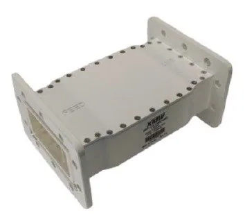
XMW BPF-CX-CF-BW C-Band Bandpass Filter Series
The XMW BPF-CX-CF-BW series is a family of C-band bandpass filters offered with six selectable passbands, from the full 3700-4200 MHz downlink block through 3720-4200, 3800-4200, 3820-4200 and 3900-4200 MHz down to a 4000-4200 MHz option. Corresponding bandwidths are 500, 480, 400, 380, 300 and 200 MHz, with in-band insertion loss quoted between 1.3 dB and 1.7 dB maximum depending on variant. All BPF-CX-CF-BW filters use CPR229 waveguide flanges for direct earth station feed integration.
Key Features
- Six selectable C-band passbands so the filter can be matched to your spectrum plan
- Bandwidth options from a full 500 MHz block down to a narrow 200 MHz window
- Maximum in-band insertion loss between 1.3 dB and 1.7 dB depending on the variant chosen
- CPR229 waveguide flanges allow direct insertion into standard C-band feed chains
- Narrower variants trade usable spectrum for stronger rejection of lower adjacent energy
- Passive waveguide construction with no power, tuning or in-service maintenance requirement
Technical Specifications
Typical Applications
- C-band teleport and gateway earth station receive feed chains
- Terrestrial interference mitigation at fixed satellite ground stations
- Broadcast and video distribution C-band downlink receive systems
- Maritime and offshore energy C-band VSAT installations
- Remote mining and pipeline site satellite communications terminals
- Government and enterprise C-band backhaul and network hubs
Choosing the Right C-Band Bandpass Filter Passband
The whole point of the BPF-CX-CF-BW series is that you do not have to take one fixed passband. If your network genuinely uses the full conventional C-band downlink, the 3700-4200 MHz variant with 500 MHz of bandwidth preserves everything. If interference is arriving from below the band, stepping up to a 3800-4200 or 3900-4200 MHz variant moves the lower skirt away from the wanted spectrum and pushes far more attenuation onto the offending energy. The 4000-4200 MHz option, at 200 MHz bandwidth, is the most aggressive choice and is appropriate when your carriers all sit in the upper part of the band. The right selection begins with a spectrum survey, not a catalogue page.
Terrestrial Interference and the C-Band Downlink
C-band earth stations increasingly share their neighbourhood with terrestrial mobile networks operating immediately below the satellite downlink. Where those services are close by, a receive chain can be desensitised by out-of-band energy long before any wanted carrier is affected on paper, and the symptom is often a puzzling loss of margin that no antenna alignment fixes. A waveguide bandpass filter fitted ahead of the low-noise amplifier is the standard remedy, because it removes the offending energy before it can compress the first active stage. The BPF-CX-CF-BW series exists precisely for this job, with narrower variants offering progressively better protection at the cost of usable downlink spectrum. Consult the specification sheet for the detailed rejection curve of each variant.
Insertion Loss, G/T and Where to Fit the Filter
Any loss placed ahead of the low-noise amplifier adds almost directly to system noise temperature, so the 1.3 to 1.7 dB maximum in-band insertion loss of the BPF-CX-CF-BW family is a figure worth including in your G/T calculation rather than ignoring. In most installations that penalty is far smaller than the desensitisation the filter prevents, which is why filtering ahead of the LNA remains normal practice at interference-affected sites. Keep the waveguide run between filter and amplifier short, use correct gaskets and full bolt sets on the CPR229 flanges, and weatherproof outdoor joints in line with the rest of the feed. Verify the installed response with a sweep and record it for the site documentation.
Why Buy XMW C-Band Waveguide Filters from GCCSAT in the UAE
GCCSAT is a UAE-based satellite communications integrator supplying RF components to teleports, broadcasters, energy operators and government users across the GCC and wider Middle East. Terrestrial interference into C-band is a live issue across the region, and we help customers work through it properly: reviewing spectrum measurements, selecting the right BPF-CX-CF-BW variant for the actual interference profile, and confirming waveguide and flange compatibility before anything is ordered. We can supply the filters alongside feeds, LNAs, amplifiers and waveguide hardware as a single coordinated package, and we support installation, integration and commissioning regionally. Datasheets and pricing for the BPF-CX-CF-BW series are provided on request.
Frequently Asked Questions
What passband options are available in the BPF-CX-CF-BW series?
XMW lists six frequency ranges: 3700-4200, 3720-4200, 3800-4200, 3820-4200, 3900-4200 and 4000-4200 MHz, giving bandwidths of 500, 480, 400, 380, 300 and 200 MHz respectively. All variants share the same CPR229 waveguide interface, so the choice is purely about how much spectrum you need versus how much rejection you want.
How much insertion loss do BPF-CX-CF-BW filters add?
Maximum in-band insertion loss is quoted at 1.7 dB, 1.5 dB, 1.4 dB and 1.3 dB depending on the variant. Because these filters are normally installed ahead of the low-noise amplifier, that loss should be entered into your system G/T calculation. Refer to the XMW specification sheet for the loss figure tied to the exact variant you are considering.
Which BPF-CX-CF-BW variant should I choose for terrestrial interference?
It depends on where the interference sits relative to your carriers. If the offending energy is below the C-band downlink, a variant with a higher lower edge such as 3900-4200 or 4000-4200 MHz gives more attenuation, but you lose the spectrum below that edge. Start with a spectrum survey, then match the passband to the carriers you actually operate.
What waveguide flange do these C-band filters use?
All BPF-CX-CF-BW filters use CPR229 waveguide flanges on input and output, the standard C-band waveguide interface. That allows direct installation into a conventional earth station feed chain without transitions. Confirm gasket type, bolt set and outdoor weatherproofing arrangements as part of the installation plan.
Can GCCSAT advise which C-band bandpass filter suits my earth station?
Yes. GCCSAT works with earth station operators across the UAE and GCC on C-band interference mitigation. Send us your spectrum measurements, carrier plan and feed configuration and our engineers will recommend the appropriate BPF-CX-CF-BW variant, confirm waveguide compatibility and quote it as part of a complete RF front-end package. Pricing is provided on request.
Enquire About XMW BPF-CX-CF-BW C-Band Bandpass Filter Series
Our sales team will provide pricing, availability, and shipping details.
Request a QuoteWhatsAppMore VSAT RF Components
- XMW BPF-1219-400 L-Band Bandpass Filter
- XMW BPF-3423-36 C-Band Bandpass Filter
- XMW BPF-1000-30 L-Band Bandpass Filter
- XMW BPF-CF-BW (BPF-C-1 to BPF-C-6) C-Band Bandpass Filters
- XMW BPF-7500-500 X-Band Bandpass Filter
- XMW BPF-11600-1800 Ku-Band Bandpass Filter
- Times Microwave N-Type and F-Type Coaxial Connectors
- Times Microwave LMR400, LMR600, RG6 and RG11 Coaxial Cables
- Norsat OMT-KUE Ku-Band Extended OMT Transmit Reject Filter
- Norsat C-Band Band Pass Filter (BPF)
- Nexgenwave Low Ku-Band Waveguide Rejection Filter
- Jupiter Microwave Flexible Waveguide (C-Band and Ku-Band)
- ELT Systems Passive Combiner-Splitter (L-Band and S-Band)
- ELT Systems TEEL1-4007 Bias Tee
- ELT Systems XX-435000 RF Attenuator (3, 6, 10 and 20 dB)
- ELT Systems L-Band and IF-Band Active Splitter (2 to 16-Way)
- ELT Systems L-Band Active Combiner (2, 4, 8 and 16-Way)
- Actox Bias-T DC Power Injector (ABT6AN, ABT6AON, ABT6ARS)
Product Categories
- VSAT BUC
- VSAT LNB
- VSAT Antennas
- VSAT Fixed Antennas
- VSAT Flyaway Antennas
- VSAT Maritime Antennas
- VSAT KingSat Antennas
- L-Band Satellite Terminals
- Cobham BGAN Terminals
- Thuraya L-Band Terminals
- VSAT Satellite Modems
- Satellite Phones
- Teltonika Products
- Sangfor Firewall & SD-WAN
- Thuraya Accessories
- Excelerate Hybrid Connectivity
- Peplink Products
- VSAT RF Components
- VSAT Hub & Test Equipment
- Remote Site Power Systems