
- Home
- Industries
Industries
Enabling transformation and progress across a wide range of industries globally, fostering innovation and growth in every sector.
Explore all → - Solutions
Connectivity
Connecting industries worldwide with reliable satellite internet solutions, driving innovation, efficiency, and growth across all sectors globally.
Explore all → - Services
Professional VSAT & IT Services
Delivering expert VSAT and IT solutions for seamless connectivity, reliability, and performance across all sectors.
Explore all → - Products
Superior Connectivity, Trusted Solutions
Offering premium Satcom products that guarantee reliable connectivity and boost innovation across industries.
Explore all → - Coverage
WorldWide Coverage
Delivering tailored satellite services that enhance connectivity, foster innovation, and support growth in every industry.
Explore all → - About
- Blog
- Contact
XMW BPF-7500-500 X-Band Bandpass Filter
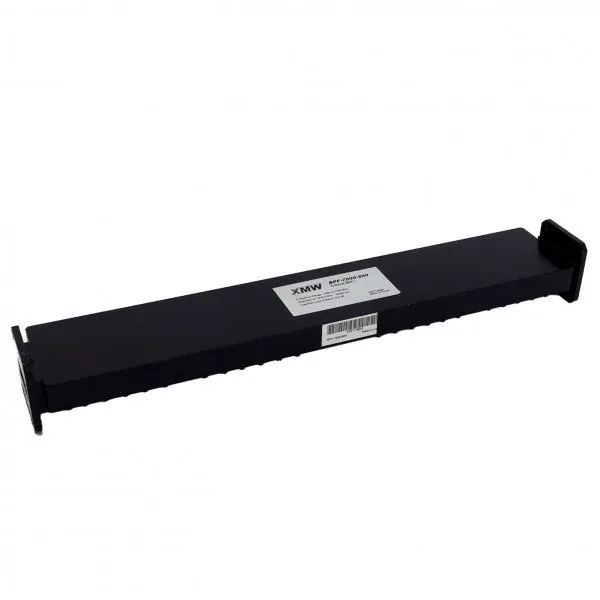
XMW BPF-7500-500 X-Band Bandpass Filter
The XMW BPF-7500-500 is an X-band bandpass filter covering the 7.25 to 7.75 GHz receive range with 500 MHz of bandwidth. It combines just 0.5 dB of in-band insertion loss with 100 dB of rejection across 7.90 to 8.40 GHz, the adjacent X-band transmit range, making the BPF-7500-500 well suited to protecting a receive chain at a co-sited transmit and receive terminal. Input and output are WR112 waveguide, and XMW notes that other frequency options are available on request.
Key Features
- Covers the 7.25 to 7.75 GHz X-band receive range with 500 MHz of bandwidth
- Exceptional 100 dB rejection across 7.90 to 8.40 GHz protects receivers from co-sited transmit
- Very low 0.5 dB in-band insertion loss preserves X-band system G/T
- WR112 waveguide interfaces integrate directly into standard X-band feed chains
- Alternative centre frequencies available from XMW to suit specific channel plans
- Passive waveguide construction with no power requirement or routine maintenance
Technical Specifications
Typical Applications
- Government and defence X-band satellite ground terminals
- Co-sited transmit and receive X-band earth stations requiring Tx/Rx isolation
- Transportable and man-portable X-band military VSAT systems
- Fixed X-band teleport and anchor station receive feed chains
- Maritime and vehicular X-band satellite communications platforms
- Disaster recovery and rapid-deployment secure communications links
Why an X-Band Bandpass Filter Needs 100 dB of Rejection
X-band government and military satellite terminals transmit and receive from the same antenna, with the receive range at 7.25 to 7.75 GHz sitting immediately below the transmit range at 7.90 to 8.40 GHz. Those two bands sit immediately adjacent to one another, yet the power difference between them can be enormous: a high-power amplifier output measured in tens or hundreds of watts against a receive signal measured in picowatts. Without deep filtering, transmit energy and its noise floor leak into the receive path and desensitise the front end. The BPF-7500-500 addresses exactly this with 100 dB of rejection specified across the full 7.90 to 8.40 GHz transmit range, which is why this class of filter is standard in co-sited X-band terminals.
Low Insertion Loss and X-Band Receive Sensitivity
Filtering ahead of the low-noise amplifier is only viable if the filter itself is quiet, because loss at that point in the chain adds almost directly to system noise temperature. At 0.5 dB of in-band insertion loss across the 7.25 to 7.75 GHz passband, the BPF-7500-500 is light enough to sit in front of the LNA without meaningfully eroding G/T, while still delivering the stopband depth the application needs. That combination, low loss in-band and very deep rejection close by, is the defining characteristic of a well-designed waveguide receive filter. When budgeting the link, include the 0.5 dB figure alongside feed, flange and waveguide run losses rather than treating the filter as loss-free.
WR112 Installation and Integration Notes
The BPF-7500-500 uses WR112 waveguide, the standard rectangular waveguide size for X-band, so it fits directly into a conventional X-band feed assembly. Inspect and clean flange faces before mating, use the correct gasket, and tighten the complete bolt set evenly, since at these frequencies a poor joint costs more than it does lower in the spectrum. Support the waveguide properly so no mechanical stress is carried through the filter body, particularly on transportable terminals that are repeatedly packed and deployed. Observe any signal direction marking on the housing. After assembly, sweep the receive chain and confirm both the passband response and the achieved transmit-band rejection, then archive the trace in the site documentation.
Why Buy XMW X-Band Waveguide Filters from GCCSAT in the UAE
GCCSAT is a UAE-based satellite communications integrator supporting government, defence and commercial customers across the GCC and the wider Middle East. We supply XMW X-band components including the BPF-7500-500 as part of complete RF front-end packages, so that waveguide sizes, flange standards and frequency plans are reconciled at the design stage rather than on site. Because XMW offers alternative frequency variants in this family, we can help match a filter to your specific channel plan instead of forcing a compromise. Our team provides integration, installation and commissioning support regionally, for both fixed teleports and transportable terminals. Datasheets and pricing for the BPF-7500-500 are provided on request.
Frequently Asked Questions
What frequency range does the XMW BPF-7500-500 cover?
The BPF-7500-500 has a passband of 7.25 to 7.75 GHz, giving 500 MHz of bandwidth in X-band, with 0.5 dB of in-band insertion loss. XMW states that other frequency options are available on request, so a variant matched to a different channel plan can usually be specified rather than adapting your system to a fixed passband.
How much rejection does the BPF-7500-500 provide in the transmit band?
XMW specifies 100 dB of rejection across 7.90 to 8.40 GHz. That is the adjacent X-band transmit range, so this figure describes how effectively the filter isolates a receive chain from a co-sited transmitter sharing the same antenna. It is the key specification for anyone selecting a filter for a transmit and receive X-band terminal.
What waveguide interface does the BPF-7500-500 use?
Both ports use WR112 waveguide, the standard rectangular waveguide size for X-band, allowing direct integration into a conventional X-band feed chain. Plan for the correct flange gasket and full bolt set, and support the waveguide mechanically so the filter body carries no load, particularly on transportable terminals that are frequently rigged and de-rigged.
Where should the BPF-7500-500 be installed in an X-band terminal?
Typically in the receive path ahead of the low-noise amplifier, so that transmit-band energy is attenuated before it reaches the first active stage. The filter's low 0.5 dB insertion loss is what makes that placement practical, since loss ahead of the LNA translates almost directly into reduced system G/T and degraded receive sensitivity.
Can GCCSAT supply the BPF-7500-500 to customers in the UAE and GCC?
Yes. GCCSAT supplies XMW X-band RF components including the BPF-7500-500 across the UAE, the GCC and the wider Middle East, with engineering support for integration and commissioning of both fixed and transportable terminals. Contact our team with your frequency plan and waveguide configuration and we will confirm the correct variant. Pricing is quoted on request.
Enquire About XMW BPF-7500-500 X-Band Bandpass Filter
Our sales team will provide pricing, availability, and shipping details.
Request a QuoteWhatsAppMore VSAT RF Components
- XMW BPF-1219-400 L-Band Bandpass Filter
- XMW BPF-3423-36 C-Band Bandpass Filter
- XMW BPF-1000-30 L-Band Bandpass Filter
- XMW BPF-CX-CF-BW C-Band Bandpass Filter Series
- XMW BPF-CF-BW (BPF-C-1 to BPF-C-6) C-Band Bandpass Filters
- XMW BPF-11600-1800 Ku-Band Bandpass Filter
- Times Microwave N-Type and F-Type Coaxial Connectors
- Times Microwave LMR400, LMR600, RG6 and RG11 Coaxial Cables
- Norsat OMT-KUE Ku-Band Extended OMT Transmit Reject Filter
- Norsat C-Band Band Pass Filter (BPF)
- Nexgenwave Low Ku-Band Waveguide Rejection Filter
- Jupiter Microwave Flexible Waveguide (C-Band and Ku-Band)
- ELT Systems Passive Combiner-Splitter (L-Band and S-Band)
- ELT Systems TEEL1-4007 Bias Tee
- ELT Systems XX-435000 RF Attenuator (3, 6, 10 and 20 dB)
- ELT Systems L-Band and IF-Band Active Splitter (2 to 16-Way)
- ELT Systems L-Band Active Combiner (2, 4, 8 and 16-Way)
- Actox Bias-T DC Power Injector (ABT6AN, ABT6AON, ABT6ARS)
Product Categories
- VSAT BUC
- VSAT LNB
- VSAT Antennas
- VSAT Fixed Antennas
- VSAT Flyaway Antennas
- VSAT Maritime Antennas
- VSAT KingSat Antennas
- L-Band Satellite Terminals
- Cobham BGAN Terminals
- Thuraya L-Band Terminals
- VSAT Satellite Modems
- Satellite Phones
- Teltonika Products
- Sangfor Firewall & SD-WAN
- Thuraya Accessories
- Excelerate Hybrid Connectivity
- Peplink Products
- VSAT RF Components
- VSAT Hub & Test Equipment
- Remote Site Power Systems